Category Archives: Uncategorized

Minimum Viable Operational Overhead

Operational overhead is all the costs you incur just to keep your app running, totally separate from initial and ongoing development. This is all the behind-the-scenes work necessary to support ongoing operation: updating special models (“categories”, “countries”, etc.), auditing capacity consumption, re-running failed scheduled tasks, granting access or privileges, etc. It’s uninspired busywork that we can’t seem to escape. It ends up relegated to your on-call rotation and is generally a drag and a distraction from future development.

Nobody likes operational overhead, yet rarely do engineers budget time into their project plans to build features that help reduce it from the beginning. Why not? Most often the refrain is “Sounds great, but we don’t have the time to build that.” But make no mistake, these same engineers will spend vastly more time maintaining the systems they build than building them in the first place! When the time comes for you to take some operational action, the work you’ve done in advance to minimize overhead determines whether it’s a just quick series of clicks or a nightmarish slog through the application database console. If it’s the latter, then you are setting the team up for lengthy interruptions and costly outages.

Operational overhead is another kind of tech debt, where you are paying for “quick” development now with operational work later. I’d argue that allowing operational overhead is right up there with avoiding unit tests: it seems fast, but is actually slow. Worse, operational overhead is an enormous morale drain.

Minimum Viable Operational Overhead

Minimum Viable Operational Overhead, then, is the philosophy of building systems that require the lowest amount of operational overhead possible while still working. The “minimum viable” part is in there to remind us that customers must come first, and in practice any useful system will have operational overhead. But when you prioritize reducing operational overhead, your customer is your future self. Making sure to budget for this kind of work will help you produce higher-quality systems and allow you to move more quickly in the future.

The actual techniques you should use to reduce operational overhead are too various and situational to list, but I have two favorites that always seem to be applicable. The first is to automate everything. You should try to minimize the number of operational tasks that require (or encourage) the least bit of creativity or analysis during execution. If it requires you to think about how the pieces fit together, then the context switch will be worse and you run a greater risk of making a mistake along the way. Even if it seems simple, write a simple script that does the task and document the arguments extremely well. Make sure the usage is described in your runbook and it’s copy-pasteable. Better, just build the copy-pasteable part into the app — it can be easier to just handle the special case than it is to document it. The more brainless you can make your operational interruptions, the better.

A common trap to fall into here is to think “eh, this is a one-off, I’ll automate this the next time it comes up.” Don’t do this. It’s hard to tell at the outset how many times you might have to redo an operational task. The best case is that the next time it only takes you 5 seconds, but the worst case is that you’ve rigorously done a one-off. Script it this time.

The second key technique is to make a UI. I can hear the grumbling already, but honestly, it’s not that difficult to attach a trivial web UI to the service or to add a few views to an existing application. When you do this well, it pays off in spades. It is incredibly powerful to be able to click a link or fill out a short web form to complete an operational task, especially the kind that involve hairy curl requests or manipulating complex database records. This also tends to make operational tasks almost self-documenting, because you have a place to write a document that lives right alongside the code itself. And since it’s an actual code artifact integrated right in with the existing internal API, it’s much easier to keep it up to date and functioning. (Write tests for your admin UIs!)

But the best part is that you will find that these internal-facing admin UIs grow like weeds, accumulating more and more command / control / monitoring features over time. It’s often not the first button that’s the big win — it’s that by taking the time to create a trivial web UI now, you are dramatically lowering the activation energy for future efforts that just need a place to put one more button. Eventually you’ll have a whole control panel full of them.

Thanks to Dmitri, Jack, and Sarkhan for reading and editing this post!

Custom Bench for Shapeoko 2 (+ Upgrades)

complete-bench

I bought a Shapeoko 2 about six months ago. One of the things the mistakes I made on day one was the lack of a permanent, high-quality bench for it to live on. Not thinking ahead, I built my SO2 on top of a knock-down bench I built for doing “dirty” tasks – it’s just a sheet of 3/4″ particle board on top of two sawhorses. Permanently attaching a CNC machine to a floppy surface turns out not to be the best call, and I’d rather have the dirty bench available for assembly projects anyways.

So it was time to build a permanent bench. Here are the key features I decided on:

  • Sturdy. No sagging surface or rickety legs. I want this thing to be able to survive the rigors of daily use and future moves.
  • Mobile. It’s got to be on wheels so I can push it up against a wall when I need to.
  • Extra storage below. I’ve accumulated a few boxes of SO2 stuff that are best stored with the machine.
  • Convenient hookups. Should have on-board power strip and integrated cord. Also, let’s add in a permanent vacuum line so we can put a debris collector on the toolhead.
  • At least moderately attractive.
  • Cheap.
extrusion_cart_frame_render

Concept render of aluminum extrusion version.

While I first considered building a bench out of aluminum extrusion, after spending a few hours planning and pricing, it wasn’t going to work out. It would be too expensive and not that sturdy. It also didn’t help that the materials would have to be special ordered and couldn’t easily be cut with the tools I have on hand.

Ultimately, I settled on regular dimensional lumber for the project. I don’t usually consider 2×4 benches to be terribly attractive, but by squaring them off to 3″ x 1-1/4″ with my table saw, I ended up with a much more acceptable-looking piece of wood. Also, instead of butted-and-bolted joints, I decided to try out some table saw joinery techniques and opted for a half-lap approach. The best part of dimensional lumber is that 2x4s cost less than $3 / 10′ and are available at the local hardware store.

cart_frame

Frame all glued up and put on wheels.

The design itself is very simple. The four corner posts are made of 4x4s resawn down to 3″x3″. All the horizontal beams are resawn 2x4s. Both the posts and beams have half-laps cut in their ends using my table saw’s crosscut sled and a dado stack. (The corner posts are half-lapped from two sides.) I added some midspan supports to make the top and shelf even sturdier; those are connected with glue and pocket screws. The rest is all just wood glue.

torsion-box

Inside of the torsion box before the skin was glued on.

The bottom shelf is a piece of 1/2″ MDF, but the top of the bench is more exotic. It’s a 24″x48x4″ torsion box made from 1/2″ MDF, including the skins. Inside, there’s a grid of ribs on 6″ centers. The ribs fit together with half-lap joints as well, which I cut on my table saw’s crosscut sled with an improvised indexing jig to get reliable spacing. All together, this work top is probably the single sturdiest thing I’ve ever built, and it is not absurdly heavy. It’s exactly what I want to serve as the basis for my CNC. The torsion box is attached to the frame with a few brackets and screws. Put together, the cart has a very solid feel to it. Finally, there’s a set of locking casters on the bottom of the corner posts to make it mobile.

assembled-cart

Fully assembled glamour shot

compartment-open-2

compartment-closed

After I had the cart rolling around, it was time to transplant my Shapeoko 2. This part had me a bit worried, since the existing parts had been wired together in place and didn’t have much slack. I ended up taking advantage of a little extra space underneath the torsion box by making a “hidden” compartment to stash the spindle and motor power supplies. I attached a power strip to the frame and ran the cable out through a hole in the bottom, then made a hole in the torsion box surface for cables from the control panel to reach inside. This turned out to be a huge pain, since I had to go through one of the vertical ribs to get inside of the frame. If I ever do something like this again, I’m definitely going to plan in advance and make the holes before gluing the skins.

In all, I ended up routing the motor supply, spindle supply, and e-stop hookup down through the box, into the frame, and into the secret compartment. This really cleans up all the stuff that used to hang around next to the control panel and makes it easier for me to slide the Shapeoko2 itself as far to the edge of the work surface as possible. (This is important because I am planning to eventually extend the machine to 1000mm in the x-axis, and that just about fills the entire width of the surface.)

drag-chain-detail-rearloc-line-frontThe final touch was the debris collection system. I saw a forum post about using Loc-Line to make a nice debris collector that hangs out near the toolhead and decided this was the approach for me. The only part I didn’t like was how the collector moved with the toolhead. This configuration makes it hard to position the collector nozzle close to the work piece without eventually crashing into it. Instead, I decided to mount the Loc-Line in a fixed configuration that didn’t move in the Z-axis. To do this, I whipped up a mounting plate that bolts onto the back of the X-carriage and provides a hole pattern to mount the Loc-Line adapter. It also provides a vertical slot mount the X drag chain horizontally. The other end of the drag chain connects to a vertical “mast” with another long slot; the whole thing bolts to the “accessory rail” I added behind the X Makerslide. This worked great, especially if you ignore the ungainly stack of spacers and washers I needed to make the bend of the drag chain work out.

vacuum-hookupThe PVC pipe tee on the X-carriage connects to a piece of corrugated hose, which connects to a tall piece of pipe bracketed to the side of the cart. That goes all the way down to the foot of the cart and to an adapter that my shop-vac’s hose can plug right into. It works great! The only thing I would change would be to use larger diameter PVC pipe – the shop vac sounds like it’s struggling a bit due to the constriction of the current setup.

Pain box part 2: When in doubt, add watts

In my last post, I introduced my painbox project and talked about the prototype I’d assembled so far. The basic functionality was there, but the performance was subpar. The device itself was also a giant mess, making it hard to iterate on. Time to make some improvements.

New parts

I decided to try to improve performance by upgrading the underperforming components. The most important performance aspect is the “cold” side temperature – you’ll recall from the last post that it never really got that cold at all. There are two reasons for the poor performance: the TEC wasn’t pumping much heat, and the passive heatsink on the hot side of the TEC couldn’t bring it close enough to ambient. Luckily, both of these problems were easily solved with a little money. I found a much higher wattage TEC and a CPU cooling heatpipe/heatsink/fan combo to go with it. Specifically, the heatsink has a dissipation rating that matches that of the TEC, which should hopefully allow ideal performance.

heatsink

Cleaning up the project board

In the process of switching out the TEC and heatsink, I decided to redo all the plumbing and component organization as well. First off, I wanted to install smaller reservoirs to drop the volume, thinking this would improve time to target temperature. I swapped out the old reservoirs made with PVC straight tees for pre-threaded PVC corner tees. I’d estimate this drops the volume of water in the reservoir by about 50%, and it uses fewer pieces and less space to boot.

Next, I drilled holes to mount the “hot” heat exchanger to the project board. Nothing too fancy here, just four holes and some zip ties to keep the water block, TEC, and heatsink in place. At the same time, I mounted the “cold” TEC and the new giant heatsink to the project board with some long #4-40 screws.

Finally, I redid all the plumbing. The vinyl tubing I’d used is much stiffer than expected, making tight bends and precise part positioning difficult. To replace it, I used pieces of 3/8″ copper tubing bent with my tube bender and joined to other parts with short lengths of vinyl tubing as couplers. The result is much, much cleaner and more compact. I also moved the pumps to be directly in line with the inputs to the radiator.

Here’s how it looks after all the work:

painbox_clean

The plumbing is very neat, though the wiring is still a giant mess. I’m going to have to implement a good strategy there soon.

Performance

I could hardly wait to try it out again after hooking up that giant heatsink. I repeated my earlier setup of thermistors taped down to radiator pipes with pipe insulation, then turned it on and monitored results. Here’s what I got:

Power was switched off at 20 minutes, though monitoring continued to as a way to gauge how quickly temps went back to equilibrium.

Much better! We can now see that the cold side actually does get cold: down to about 16C after 10 minutes. I let it run for a while and then gave the radiator a touch. I found that the hot side still felt a tad too hot, making it impossible to really judge if it was “working”. So then I turned it on again and watched the temperature readout until it was at a desirable hot temp, and quickly gave it another try. It definitely felt hotter than it actually was! It’s very encouraging that the effect can be felt when the temps are in the right spot, even if that’s only briefly. Without closed loop temp control, the temps will never be where they’re supposed to be, so that’s definitely the next item on my todo list.

Temperature sensors

Another issue is temperature sensor accuracy. Right now, I’m relying on spherical thermistors pressed against cylindrical copper pipes and held in place with adhesive pipe insulation. Contact between the sensor and the pipe is really negligible, meaning that the temperature I’m sensing is the temperature of the air pocket between the pipe and the insulation. That air pocket is being heated/cooled by air-to-pipe conduction only. In practice, this means the temperature I’m reading back is not the same as the pipe’s surface temperature, and therefore does not reflect what a user would feel. Not good!

I did a quick test of immersing one of the thermistors in the water of the cold loop. In that case, the reading basically agreed with the one taken from the radiator surface using my non-contact thermometer. Interestingly, this means that the pipe surface temperature is basically equal to the water temperature, and I should be able to measure that temp by just putting the sensor in the water. I’m going to figure out a way to permanently install the sensors through the walls of the reservoirs.

Building a Dune “Pain Box” with the Thermal Grill Illusion

I’m a big fan of the Dune series, so when this post about the Thermal Grill Illusion popped up in my feed reader, I was immediately hooked. For those of you who are not acquainted with the Dune franchise, the “pain box” – which is never actually named in the series – is a device which causes an excruciating burning sensation without actually producing any injury.

Why is this a cool thing to have in the real world? Well, first, it’s an homage to the series, and I imagine other fans will get a kick out of it. Second, I find the idea of having a source of injury-free pain intriguing from a willpower standpoint – how long can you intentionally experience discomfort, even if you know it’s causing you no damage? Lastly, constructing it requires a mixture of electronics, mechanical engineering, and presentation, which puts it squarely in the middle of all my interest categories.

Overall design

What I’m going for is an enclosed box with a hand-sized (4″ x 8″ x 3″) opening. The bottom of the opening will be the illusion surface – what I’m referring to as the “radiator”. The box should be as small as possible for portability and overall presentation. It will have to be plugged in from a power consumption standpoint. It needs to be able to produce a hot temperature of ~41 degrees C and a cold temperature of around 18 degrees C, and I’d prefer not to use large reservoirs as the heat source. (See portability requirement.) Also, this device has potentially weird safety aspects, so it needs to be designed such that it’s hard for it to actually hurt someone. This means temperature feedback and some way to remove danger or alert the user. And lastly, I’d like to be able to make it on my Shapeoko 2 CNC machine, which limits the size of any single component to about 12″ x 12″.

Given that I’m going for compactness and simplicity, the most obvious source for both heating and cooling is a device called a thermo-electric cooler, sometimes called a Peltier. The basic concept is that it’s a solid state heat pump, where heat is pumped from the cold side to the hot side. The colder you make the hot side, the colder the cold side will get. Flip the direction of the current, and the device reverses the flow of heat.

How exactly the heat from these devices will be transferred to a user’s hand is still up in the air. Generally speaking, achieving the desired temperatures and making sure they get to the user is really the core challenge of the whole device. The rest is just tidiness and presentation.

Version 1 (Failed)

Immediately after I decided to use TECs for my hot/cold source, I bought a 5-pack of them from Amazon. (I was surprised by how cheap they were, but it turns out that might not have been a good thing. More on that later.) The next question is how to distribute the hot and cold. I’ve got a fair amount of experience making printed circuit boards on my CNC, and I know that lots of people make PCB heater boards (commonly seen on 3D printers, for instance). If a PCB could transmit heat, why not cold as well?

I designed a very simple PCB that is really just two large, interleaved copper pours connected to a space for a TEC and heatsink. The idea was that heat or cold would flow through the copper, since it’s highly conductive. It’s also a crazy simple and compact design, so I was pretty excited to produce it. Here it is, all assembled:

radiator_pcb

Turned out great! Except it completely failed to transmit heat. In fact, while the pours basically stayed at ambient, the back side of the board right under the TECs got really hot or really cold! It would seem that the thickness of copper on a standard PCB blank is way too thin to be a good conductor. Oh well, into the bin and onto the next alternative.

(Side note: the PCB heaters I alluded to earlier are not radiators of heat per se. The current being pumped through the traces on the board is what actually creates the heat in the first place.)

Version 2 (work in progress)

The new design I’m working on now swaps the PCB radiator for one made of copper tubing. Small diameter copper tubing is very affordable, easily cut and bent, and highly heat-conductive. To actually deliver heat/cold to the array of tubes that will make up the radiator, I’m using two closed-loop water heater/chiller systems.

For each loop, the basic design is a TEC strapped to a water block, with the loop looking like water block -> radiator -> simple reservoir -> aquarium pump. The TEC on each loop is configured to either heat or cool the water, which in turn heats or cools the copper tubes. Here’s my bench test of this setup:

2015-02-05 21.25.01-2

Note that my radiator is currently a proof of concept made from 3/8″ copper tube sections bridged together with 5/16″ ID vinyl tubing. I’d hoped that this tubing technique would replace the need for expensive copper plumbing fittings, but unfortunately the tubing kinks at a much larger radius than i’d like to have for good spacing. I also bought a cheap tube bending tool with the hopes that I could use that to make what I need, but discovered that the tube bender also had an overlarge bend radius! For now, I’m going to leave it alone and brainstorm alternatives.

While early qualitative testing was promising, it’s certainly not producing the level of discomfort I’m hoping for. (Ha.) Two major problems here: the hot side actually eventually gets too hot, and the cold side never quite gets cold enough. To help quantify this poor performance, I wired up a pair of thermistors and an Arduino Pro Mini to serve as a temperature logger. Here’s what the data from that logging session looks like:

image

Good news: the hot side gets hot. That is the end of the good news. Bad news: it takes over an hour for the hot side to reach its apparent max temp of 42.4 degrees C. Worse news: the cold side does awful. It gets a teensy bit cold during the first few minutes, but then eventually actually starts to increase the temp over ambient in the long run!

I think this poor performance reflects a handful of problems:

  • The hot loop just doesn’t have the pumping ability to move heat fast enough. The cold side of the TEC gets pretty cold, and that’s probably because the water in the hot loop makes up a pretty decent heat sink, even without an outlet for all that heat.
  • The cold loop doesn’t have powerful enough heatsinking on the hot side of the TEC to overcome the self-heating effect. This explains the slight drop and then long-term rise in temperature. It is also entirely possible the cold loop TEC has burned out due to overheating.
  • There is probably too much water in each loop. Between the lengths of tubing and the fairly oversized reservoirs, this is adding more mass that has to be heated or cooled, slowing down the desired temp changes.
  • The TECs I bought are under-rated for what needs to be done. I’ve been reading accounts of folks who turn on their TECs and immediately see frost on the cold side, and I’ve never come close to seeing that.

Overall, despite flaws, this design seems like it has promise. The next steps are:

  • Experiment with a more expensive / higher rated TEC unit to see if the performance is better. We’re only talking like $12 each here, so not a deal breaker.
  • Replace the janky heatsink/fan combo on the cold loop with something professionally designed to remove a lot of heat.
  • Experiment with running two TECs and waterblocks both in serial and in parallel to see if it improves the time-to-target-temperature and max delta-T
  • Prototype a feedback controller to allow each loop to hold a target temperature
  • Experiment with techniques to make a denser radiator grid

Epic Workbench Part 1

A few months back, we moved out of our apartment and into a rental house. Among the many great things about the new place was the two-car garage. With only one car, what’s a suddenly space-rich maker to do? Set up a workbench, of course.

Initially, I was planning to design a bench out of plywood that would tab-and-slot-and-screw together. I got as far as initial sketches in OpenSCAD before I decided it was just going to be too much work to design the bench I’d want to have. My search for alternatives took me here, which looked awesome, but was far too expensive. Luckily, that page lead me here, which introduced me to the world of galvanized steel fence posts.

Finally, the sweet spot: a linear construction material that’s strong, rugged, locally available, and best of all, cheap! Even the fittings (1, 2) are very affordable. (Unlike, say, galvanized steel threaded pipe, which can beggar you in a single hardware store trip.)

I settled on 1 3/8″ fence posts as my material of choice then got to designing. Feature-wise, I’m looking for a large worktop, with ample storage above and below, and lots of vertical space for pegboard, which will end up being tool storage. Add to that a securely-anchored bench vise, permanent power strips, and some bright lighting, and you’ve got my perfect “mostly electronics, sometimes random mechanical” workspace.

My usual process with 3D design projects these days is to buy samples of the components I’ll be using so that I can take measurements and make reasonable estimations for how things will turn out. In this case, I bought a single 10-foot length of pipe, one tee fitting, and one elbow fitting.

While I was at the hardware store, I bought some metal-cutting reciprocating saw blades so that I could actually cut the pipe I’d bought. I’d really rather have used a tube cutter, but the one I already own is 1/2″ too small, and a pack of blades is about 1/3 the cost of an appropriately-sized tube cutter from Amazon. I was pleasantly surprised by how quickly those blades chopped up the pipe: perhaps 45 seconds per cut, a totally reasonable amount of time for the number of cuts I had to make.

Over the next week or so I spent my daily commute time designing the workbench in OpenSCAD. Here’s a render of what I came up with:

workbench_render

Notable features:

  • Everything is laid out around unbroken vertical tubes that run up the back, making up the legs and the rear supports of the top shelf. I figured this would lead to the strongest overall design.
  • The fittings are necessarily taller than the pipes themselves, and since there are so few of them (at different heights, even!) it’s necessary to make a custom spacer/clamp component in order to make a level worktop. No worries, though, as I can easily just CNC all the spacers and clamps I need. Also, once I have the spacer/clamp thing nailed down, I can easily use copies of that part to make mounting brackets for all the pegboards.
  • I found this great calculator called The Sagulator that helps you compute how much a surface of varying thickness will bow given how it’s supported, etc. This was really helpful in estimating eventual performance and influencing part placement.
  • All the tee fittings have very convenient screw holes stamped into them for securing the “cross” part to the pipe. I’m planning to put screws in all of these to make the frame sturdier and easier to re-assemble if I ever have to take it apart. (For example, to move to a new house.)
  • The worktop and shelves will still be CNC-cut, but mostly just because I want some rounded corners and “eyeballed” cuts stress me out. (What are the chances I would be able to maneuver a 7’x2.5′ piece of plywood on a bandsaw, anyways?) One major advantage of this approach is that I’ll be able to drill very precise pilot holes for all the spacer/clamp assemblies, making it much easier to assemble when all the parts are cut out.
  • I’d like to make use of adjustable feet so that I can precisely level the whole workbench, but I haven’t yet figured out how to adapt commercially-available leveling feet to the ends of my pipes. I think I’ll end up CNCing some inserts that I can pound in and then thread in the leveling feet.

As of now, I think the design is basically finalized. I bought all the pipe and fittings I need and I’m ready to start fabricating. Stay tuned for updates on actual progress!

Creating animated GIFs from OpenSCAD

animated

I do almost all my physical designs in OpenSCAD, and sometimes I want to post an image of my models. Since these are 3D models we’re talking about, a static image is kinda insufficient, but an animated GIF can do the job nicely.

OpenSCAD has an animation feature which allows you to create models that can mutate relative to time. While it’s primitive, it lets you slap a time-based rotate around your top-level object to get a nice 360 spin view. Then, when you select Animate from the View menu, the display will animate.

To go from the animated view in OpenSCAD to an animated GIF, check the “Dump Images” checkbox in the animation controls. This will cause each frame to be written out to a PNG file in the same directory as the .scad file. I like to check the box and then wait for the animation to repeat a little more than once to be sure that all the images have been dumped.

Once all the images are on disk, converting them into an animated GIF is surprisingly simple if you have ImageMagick’s convert utility. Here’s the command I use to convert a bunch of frames into an animated GIF:

convert 'frame*.png' -set delay 1x24 animated.gif
view raw gistfile1.sh hosted with ❤ by GitHub

The only real gotcha here is the “-set delay” option, which has a cryptic syntax: NxM means “N units of 1 second divided by M”. Thus, “1×24” means 1/24 of a second. I’ve had the most success setting the frame delay this way, but there are probably other ways to do it.

Using an OpenSCAD shape as the board outline in EAGLE

I’ve been working on a Charlieplexed LED analog clock. The finished product will be an artfully routed PCB in a clear acrylic enclosure. Since the PCB will be the centerpiece, I want it to be pretty cool looking, including an interesting outline. The design I’m going for pictured below. It’s the union of four different rotations of the convex hull of a central circle and a smaller outer circle. Simple, right?

scad_version

While EAGLE is a pretty capable CAD package, it stops short of making it easy to lay out complex shapes like this one. On the other hand, OpenSCAD is designed with exactly this use case in mind. (Check out how easy it was to make the shape above.) So we just have to find a way to get from OpenSCAD into EAGLE. Should be simple!

OpenSCAD supports exporting 2D shapes to the DXF format. Some initial Googling made it seem like EAGLE could import DXFs, but after some clicking I found myself on a plugin page that was in German and had a link to a .EXE file. (I’m on a Mac.) Not exactly what I’m looking for.

Lacking an out of the box solution, I did what any self-respecting hacker would do, and wrote a script. DXF files are text, which is helpful, though they are in an impressively goofy format. A little searching got me to the format specification, which explained how to read the sets of points that formed line segments. With the points in hand, I had my script output a set of EAGLE WIRE commands. After switching into the “dimension” layer, I pasted the WIRE commands into the command bar. Voila, I’ve got my outline!

eagle

While it works, this script is pretty hacky. It makes a bunch of assumptions about the structure of the file that might not hold in DXFs generated by programs other than OpenSCAD. But given the amount of time invested, I’m pretty comfortable with the results!


Cellular Chronometer Part 1: Reversing the Game of Life

I’m designing an LED matrix clock that plays Conway’s Game of Life to evolve a representation of the current time. See the whole series of blog posts about the project here.

The very first step of making the Cellular Chronometer is figuring out how I’m going to make the clock display the time. As a quick refresher, Conway’s Game of Life is what’s called a “cellular automaton“, which is a set of simple rules that’s played over a grid of cells, each of which are alive or dead. You process the grid with the rules and get a new grid with a different set of cells. Cellular automata are interesting because simple starting configurations can lead to really wild phenomena like self-replicating patterns and apparent movement.

But what I want to do is be able to get the game to display specific states. I want to populate the grid with a state that I know will evolve into a digital display of the current minute. The only reasonable way I could think to do this is to craft my desired state in advance and then do a search backwards – that is, in the reverse direction of the regular Game of Life – to find prior states. This happens to be a nontrivial problem. Played forwards, the Game of Life has very simple deterministic rules, but played backwards, there are an immense number of possible configurations to examine. In computer science terms, this problem is bounded by 2^n, where n is the number of cells in the grid. 2^n gets really big really fast. Not good.

Luckily, like so many other aspects of the Game of Life, work has been done trying to efficiently search for prior game states. I figured this out after two weeks of fruitless genetic algorithms experiments when a desperate Google search led me here. While the code didn’t prove useful to me, I managed to suss out that there are several existing algorithms that do what I need. The one that I best understood is called Duparc’s Method. The key win is that instead of being 2^n in the size of the pattern, Duparc’s method is only 2^n in the height of the grid! Since my grid is only five cells tall, this makes the search into a tractable problem, even if it does turn my MacBook into a proper lap-roaster.

duparc_illustration
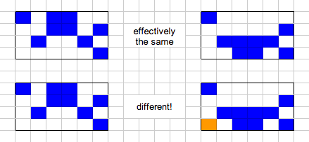
It’s hard to be 100% sure if I took the same approach as Duparc, since his original research paper is written in French. The way my algorithm works is to divide the grid in half vertically again and again until I’m working with single columns, at which point I essentially rotate the column into a row apply the same subdivision algorithm again until I reach a single cell. Single cells – both alive and dead – have a nice, cacheable method for determining all their prior states. Once I have the partial answers for a single cell, I intersect them with the answers from the neighboring cell by checking the overlap between the two. If the cells shared by the two possible solutions match, then the combined solution is also viable. Partial solutions that don’t match neighbors are discarded. This same process of merging based on overlapping cells continues back up the search tree until we reach the root, at which point we have a set of possible prior generations.

Something that took me a long time to grasp fully is that the algorithm naturally has to search in a grid bigger than the one you’re starting with. The reason for this is that while true “gardens of eden” are extremely rare, if you constrain the grid to a finite number of cells, it’s not at all hard to come up with a pattern that isn’t produceable. I ultimately came up with this sort-of logical proof to convince myself on this one:

  • In a grid of N cells, there are 2^N unique configurations
  • Some of these 2^N configurations will lead to non-unique next generations (ie, all cells dead is pretty common)
  • Therefore, it cannot be possible to generate each of the 2^N initial configurations from one of the other initial configurations.

In practice, this just means that you have to allow a “gutter” of arbitrary-valued cells around your desired image. If it’s really important to trim the excess, you just select ultimate solutions that have the extra cells as dead, since that’s the same as the border on a finite grid. The risk is that you’ll filter all the possible solutions by doing so.

As I developed this algorithm, I found that the line between “ever finishes” and “never finishes” was very fine. Most of the problems stemmed from running out of memory on my 16GB MacBook. A given target grid can have millions of intermediate states, and they need to be cached to make the algorithm run in a reasonable amount of time. The tweak that I credit with getting me all the way over the line was to discard many of the intermediate answers that, while actually unique, had the same border regions as other answers. Since the merging algorithm examines only the region of overlap between two sets of sub-solutions, any non-overlapping sections don’t actually increase your chance of finding some solution, and as such they can be discarded. This does mean that not all prior states are found, but for my purposes, I only need one.

Screen Shot 2013-09-01 at 8.57.39 PM

Along with improving the algorithm, I found that I had to tweak my font. Early on I guessed that different fonts and digit spacings would have an effect on whether a given configuration was reversible. I was surprised by how many of the configurations I wanted to generate were impossible with the grid dimensions I was enforcing. I had the algorithm report a bunch of statistics while searching so that I could see (at an aggregate level) when all possible solutions were being eliminated. I learned that particular characters were difficult to reverse, like 4s, 5s, and 0s. But the one that most surprised me was the colon I added between the hours and minutes. That guy turned out to be stubborn in some of the worst cases. In the end, I had to compromise and hand-edit certain minutes so that they would reach a prior generation.

The end result of all this hard work is 720 unique start states that will each evolve into one of the minutes of the 12-hour day. I’ll embed these states directly into the firmware for the clock so that my tiny microcontroller won’t have to do any “real” work, just run the Game of Life from each start state and advance the pointer every minute.

You can find the Ruby code for this crazy search in my GitHub repo.

The Cellular Chronometer

Making a clock seems to be a rite of passage for hobby electronics folks. The appeal is pretty obvious: straightforward functionality built with common components, and when you’re done, you have something that you can actually use in your daily life.

A little over a month ago, I had the idea for a clock project. But my clock is going to be a bit unusual. I’m designing an LED matrix clock that shows the current time by playing a different instance of Conway’s Game of Life every minute that evolves into the digital representation of the current minute. I’m going to call it the Cellular Chronometer.

This project concept hits the sweet spot for me in a number of ways. First and foremost, the challenge of making the Game of Life do my bidding is exactly the kind of deep, interesting algorithmic problem I love to tackle. I get to use all of my optimization and analysis skills to get a pretty cool result. Second, I am a sucker for designs that make use of cleverness to get a lot out of a little, so naturally I’ve been dying for a reason to build a Charlieplex, and this is the perfect opportunity. Finally, since this is something I want to actually put on display somewhere in my home or office, there’s a nice industrial design aspect to it. I want it to look well-made and polished when it’s finished.

Making an LED matrix should be pretty straightforward, as should be the “clock” behavior. I’m most familiar with Atmel microntrollers and the Arduino environment, so I’m going to use that for all the coding. Playing the Game of Life on a microcontroller is nothing new, but it’s probably impossible to search for prior game states on something with so little memory, so I’m planning to use my laptop to pre-compute all of the starting states that lead to my desired end states. And finally, I’m thinking that I’ll do the enclosure out of wood (either laser-cut or CNC-milled) so that I can finish it handsomely.

There are a lot of individual steps to this project, and I’m going to try to document them individually as I work through the project. Stay tuned for updates!

Form letter response for engineering recruiters

Like every other breathing engineer in the Bay Area, I get a lot of cold emails from random recruiters. While I haven’t yet replied to one of those messages with the below, I sure am tempted at times. Feel free to modify this template for your own purposes!

Corollary: if you are a recruiter, and you find that your reach-out emails would tick some of these checkboxes, maybe it’s time to reconsider your script.

Hello,

Thank you for your note. I am not interested for the following reason(s):

[ ] You do not include the specific name of the company you represent, which a) leads me to believe you are just canvassing and b) limits my ability to filter based on companies I don’t care for

[ ] You do not call out the specific skills I have that make me a “perfect fit”

[ ] You refer to skills or interests a) substantially in my past and/or b) clearly not part of my current role or expertise

[ ] If your CEO/CTO/VP Eng/Director of ____________ thought my background sounded good, he/she should have emailed me personally

Additionally:

[ ] I will not send you any leads because I am already personally recruiting all the good people I know

[ ] Your request that we start with a “quick call” shows a clear disregard for the work style of engineers

[ ] You appear to have misspelled my name despite having my email address to use as starting point