Monthly Archives: February 2015

Pain box part 2: When in doubt, add watts

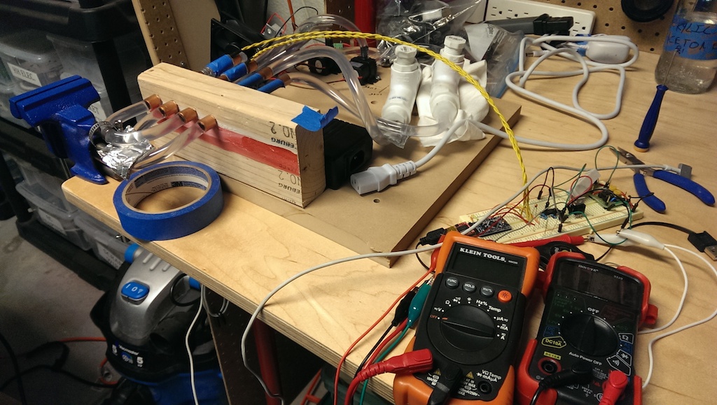
In my last post, I introduced my painbox project and talked about the prototype I’d assembled so far. The basic functionality was there, but the performance was subpar. The device itself was also a giant mess, making it hard to iterate on. Time to make some improvements.

New parts

I decided to try to improve performance by upgrading the underperforming components. The most important performance aspect is the “cold” side temperature – you’ll recall from the last post that it never really got that cold at all. There are two reasons for the poor performance: the TEC wasn’t pumping much heat, and the passive heatsink on the hot side of the TEC couldn’t bring it close enough to ambient. Luckily, both of these problems were easily solved with a little money. I found a much higher wattage TEC and a CPU cooling heatpipe/heatsink/fan combo to go with it. Specifically, the heatsink has a dissipation rating that matches that of the TEC, which should hopefully allow ideal performance.

heatsink

Cleaning up the project board

In the process of switching out the TEC and heatsink, I decided to redo all the plumbing and component organization as well. First off, I wanted to install smaller reservoirs to drop the volume, thinking this would improve time to target temperature. I swapped out the old reservoirs made with PVC straight tees for pre-threaded PVC corner tees. I’d estimate this drops the volume of water in the reservoir by about 50%, and it uses fewer pieces and less space to boot.

Next, I drilled holes to mount the “hot” heat exchanger to the project board. Nothing too fancy here, just four holes and some zip ties to keep the water block, TEC, and heatsink in place. At the same time, I mounted the “cold” TEC and the new giant heatsink to the project board with some long #4-40 screws.

Finally, I redid all the plumbing. The vinyl tubing I’d used is much stiffer than expected, making tight bends and precise part positioning difficult. To replace it, I used pieces of 3/8″ copper tubing bent with my tube bender and joined to other parts with short lengths of vinyl tubing as couplers. The result is much, much cleaner and more compact. I also moved the pumps to be directly in line with the inputs to the radiator.

Here’s how it looks after all the work:

painbox_clean

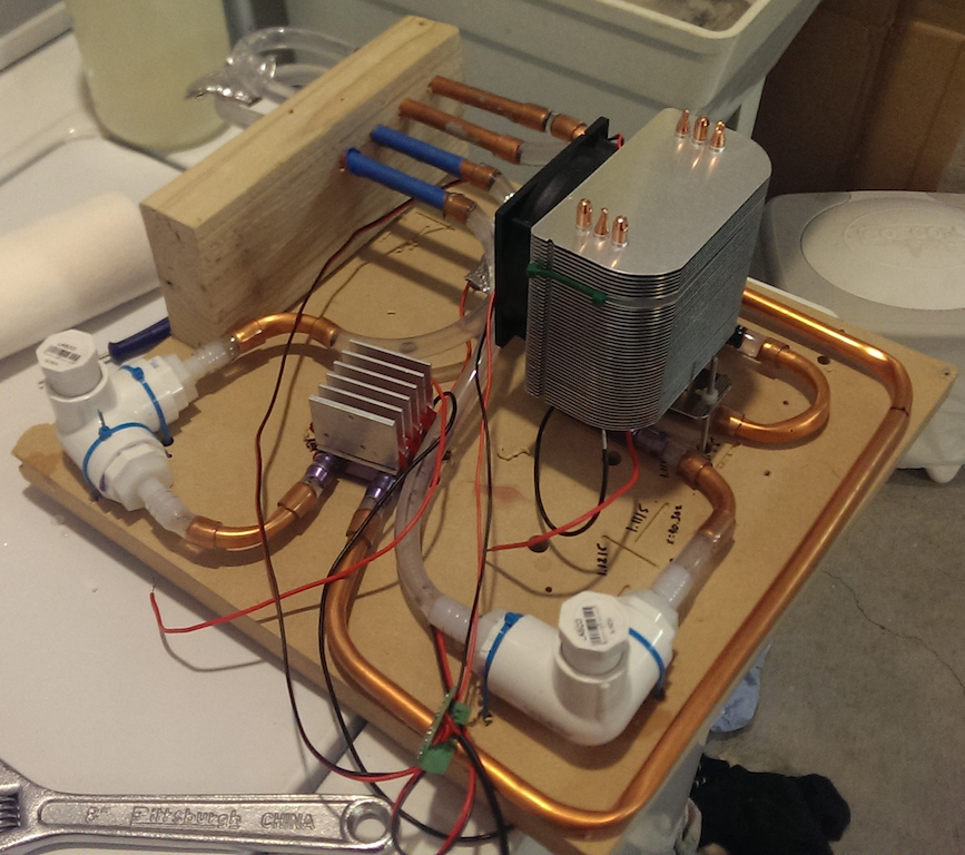
The plumbing is very neat, though the wiring is still a giant mess. I’m going to have to implement a good strategy there soon.

Performance

I could hardly wait to try it out again after hooking up that giant heatsink. I repeated my earlier setup of thermistors taped down to radiator pipes with pipe insulation, then turned it on and monitored results. Here’s what I got:

Power was switched off at 20 minutes, though monitoring continued to as a way to gauge how quickly temps went back to equilibrium.

Much better! We can now see that the cold side actually does get cold: down to about 16C after 10 minutes. I let it run for a while and then gave the radiator a touch. I found that the hot side still felt a tad too hot, making it impossible to really judge if it was “working”. So then I turned it on again and watched the temperature readout until it was at a desirable hot temp, and quickly gave it another try. It definitely felt hotter than it actually was! It’s very encouraging that the effect can be felt when the temps are in the right spot, even if that’s only briefly. Without closed loop temp control, the temps will never be where they’re supposed to be, so that’s definitely the next item on my todo list.

Temperature sensors

Another issue is temperature sensor accuracy. Right now, I’m relying on spherical thermistors pressed against cylindrical copper pipes and held in place with adhesive pipe insulation. Contact between the sensor and the pipe is really negligible, meaning that the temperature I’m sensing is the temperature of the air pocket between the pipe and the insulation. That air pocket is being heated/cooled by air-to-pipe conduction only. In practice, this means the temperature I’m reading back is not the same as the pipe’s surface temperature, and therefore does not reflect what a user would feel. Not good!

I did a quick test of immersing one of the thermistors in the water of the cold loop. In that case, the reading basically agreed with the one taken from the radiator surface using my non-contact thermometer. Interestingly, this means that the pipe surface temperature is basically equal to the water temperature, and I should be able to measure that temp by just putting the sensor in the water. I’m going to figure out a way to permanently install the sensors through the walls of the reservoirs.

Building a Dune “Pain Box” with the Thermal Grill Illusion

I’m a big fan of the Dune series, so when this post about the Thermal Grill Illusion popped up in my feed reader, I was immediately hooked. For those of you who are not acquainted with the Dune franchise, the “pain box” – which is never actually named in the series – is a device which causes an excruciating burning sensation without actually producing any injury.

Why is this a cool thing to have in the real world? Well, first, it’s an homage to the series, and I imagine other fans will get a kick out of it. Second, I find the idea of having a source of injury-free pain intriguing from a willpower standpoint – how long can you intentionally experience discomfort, even if you know it’s causing you no damage? Lastly, constructing it requires a mixture of electronics, mechanical engineering, and presentation, which puts it squarely in the middle of all my interest categories.

Overall design

What I’m going for is an enclosed box with a hand-sized (4″ x 8″ x 3″) opening. The bottom of the opening will be the illusion surface – what I’m referring to as the “radiator”. The box should be as small as possible for portability and overall presentation. It will have to be plugged in from a power consumption standpoint. It needs to be able to produce a hot temperature of ~41 degrees C and a cold temperature of around 18 degrees C, and I’d prefer not to use large reservoirs as the heat source. (See portability requirement.) Also, this device has potentially weird safety aspects, so it needs to be designed such that it’s hard for it to actually hurt someone. This means temperature feedback and some way to remove danger or alert the user. And lastly, I’d like to be able to make it on my Shapeoko 2 CNC machine, which limits the size of any single component to about 12″ x 12″.

Given that I’m going for compactness and simplicity, the most obvious source for both heating and cooling is a device called a thermo-electric cooler, sometimes called a Peltier. The basic concept is that it’s a solid state heat pump, where heat is pumped from the cold side to the hot side. The colder you make the hot side, the colder the cold side will get. Flip the direction of the current, and the device reverses the flow of heat.

How exactly the heat from these devices will be transferred to a user’s hand is still up in the air. Generally speaking, achieving the desired temperatures and making sure they get to the user is really the core challenge of the whole device. The rest is just tidiness and presentation.

Version 1 (Failed)

Immediately after I decided to use TECs for my hot/cold source, I bought a 5-pack of them from Amazon. (I was surprised by how cheap they were, but it turns out that might not have been a good thing. More on that later.) The next question is how to distribute the hot and cold. I’ve got a fair amount of experience making printed circuit boards on my CNC, and I know that lots of people make PCB heater boards (commonly seen on 3D printers, for instance). If a PCB could transmit heat, why not cold as well?

I designed a very simple PCB that is really just two large, interleaved copper pours connected to a space for a TEC and heatsink. The idea was that heat or cold would flow through the copper, since it’s highly conductive. It’s also a crazy simple and compact design, so I was pretty excited to produce it. Here it is, all assembled:

radiator_pcb

Turned out great! Except it completely failed to transmit heat. In fact, while the pours basically stayed at ambient, the back side of the board right under the TECs got really hot or really cold! It would seem that the thickness of copper on a standard PCB blank is way too thin to be a good conductor. Oh well, into the bin and onto the next alternative.

(Side note: the PCB heaters I alluded to earlier are not radiators of heat per se. The current being pumped through the traces on the board is what actually creates the heat in the first place.)

Version 2 (work in progress)

The new design I’m working on now swaps the PCB radiator for one made of copper tubing. Small diameter copper tubing is very affordable, easily cut and bent, and highly heat-conductive. To actually deliver heat/cold to the array of tubes that will make up the radiator, I’m using two closed-loop water heater/chiller systems.

For each loop, the basic design is a TEC strapped to a water block, with the loop looking like water block -> radiator -> simple reservoir -> aquarium pump. The TEC on each loop is configured to either heat or cool the water, which in turn heats or cools the copper tubes. Here’s my bench test of this setup:

2015-02-05 21.25.01-2

Note that my radiator is currently a proof of concept made from 3/8″ copper tube sections bridged together with 5/16″ ID vinyl tubing. I’d hoped that this tubing technique would replace the need for expensive copper plumbing fittings, but unfortunately the tubing kinks at a much larger radius than i’d like to have for good spacing. I also bought a cheap tube bending tool with the hopes that I could use that to make what I need, but discovered that the tube bender also had an overlarge bend radius! For now, I’m going to leave it alone and brainstorm alternatives.

While early qualitative testing was promising, it’s certainly not producing the level of discomfort I’m hoping for. (Ha.) Two major problems here: the hot side actually eventually gets too hot, and the cold side never quite gets cold enough. To help quantify this poor performance, I wired up a pair of thermistors and an Arduino Pro Mini to serve as a temperature logger. Here’s what the data from that logging session looks like:

image

Good news: the hot side gets hot. That is the end of the good news. Bad news: it takes over an hour for the hot side to reach its apparent max temp of 42.4 degrees C. Worse news: the cold side does awful. It gets a teensy bit cold during the first few minutes, but then eventually actually starts to increase the temp over ambient in the long run!

I think this poor performance reflects a handful of problems:

  • The hot loop just doesn’t have the pumping ability to move heat fast enough. The cold side of the TEC gets pretty cold, and that’s probably because the water in the hot loop makes up a pretty decent heat sink, even without an outlet for all that heat.
  • The cold loop doesn’t have powerful enough heatsinking on the hot side of the TEC to overcome the self-heating effect. This explains the slight drop and then long-term rise in temperature. It is also entirely possible the cold loop TEC has burned out due to overheating.
  • There is probably too much water in each loop. Between the lengths of tubing and the fairly oversized reservoirs, this is adding more mass that has to be heated or cooled, slowing down the desired temp changes.
  • The TECs I bought are under-rated for what needs to be done. I’ve been reading accounts of folks who turn on their TECs and immediately see frost on the cold side, and I’ve never come close to seeing that.

Overall, despite flaws, this design seems like it has promise. The next steps are:

  • Experiment with a more expensive / higher rated TEC unit to see if the performance is better. We’re only talking like $12 each here, so not a deal breaker.
  • Replace the janky heatsink/fan combo on the cold loop with something professionally designed to remove a lot of heat.
  • Experiment with running two TECs and waterblocks both in serial and in parallel to see if it improves the time-to-target-temperature and max delta-T
  • Prototype a feedback controller to allow each loop to hold a target temperature
  • Experiment with techniques to make a denser radiator grid