I spent my evenings over Memorial Day weekend working on a customized fixture designed to make programming and testing the electronics of our Question Block Lamp really easy. As part of our plan to bring the lamps back into production, we decided that a custom programming fixture would go a long way towards helping our outsourcing partner get exactly what we want quickly and without the difficulty of communication. (Emailing back and forth to China is actually pretty expensive – a simple back-and-forth exchange can take days, thanks to the time difference.)
Once we decided to build this device, I jumped in and started designing. I had a few clear design criteria:
- It should be durable. It will be used to program thousands of units. (Hopefully, tens of thousands!)
- One part or another will ultimately break down, so it has to be modular and easily repaired, particularly by someone other than me.
- It should be incredibly intuitive to use. After all, it’s not even clear that the people using it will speak English!
Here’s what I ended up building:

The interface
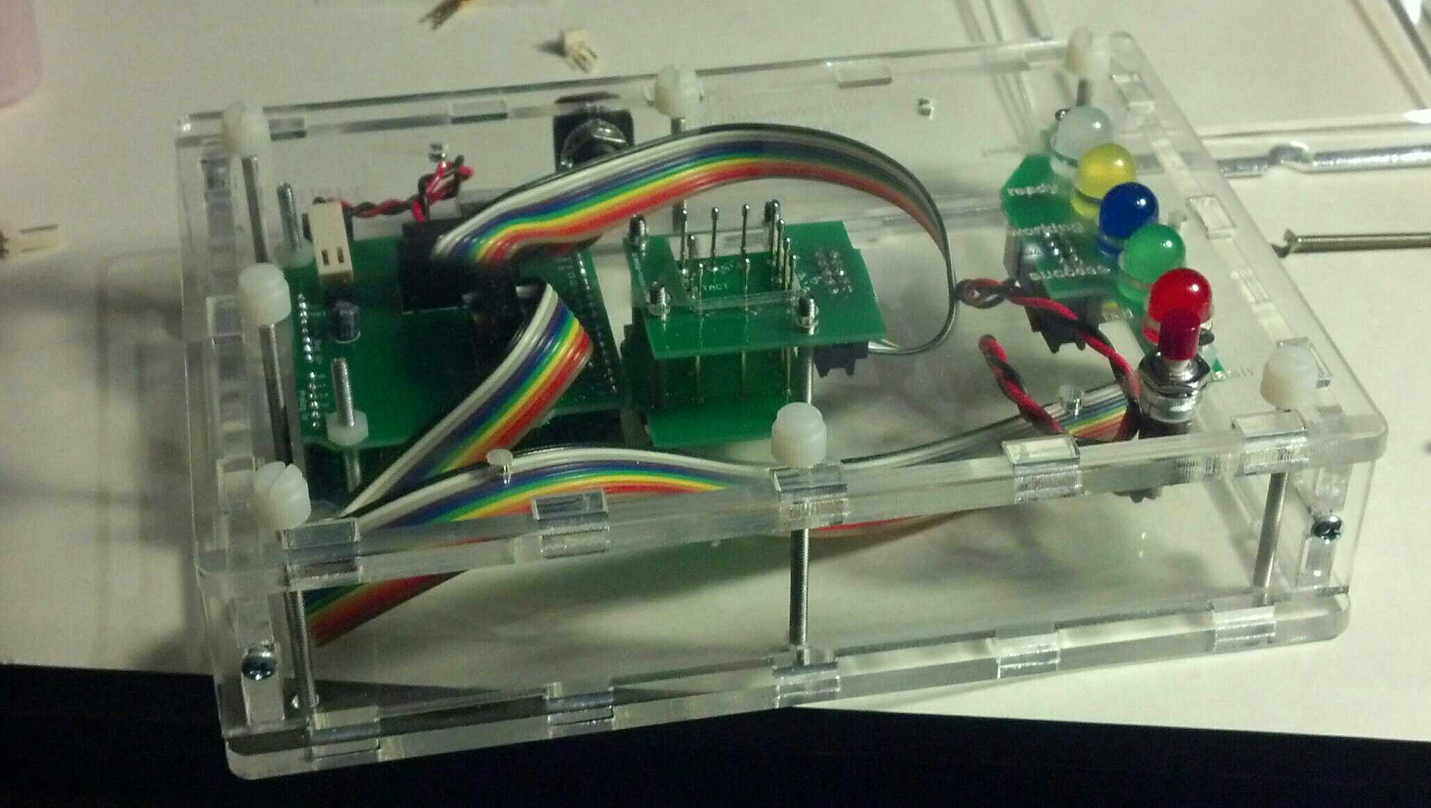
The interface is very simple. The strip of LEDs down the right hand side indicate the state of the programmer. The top one is just power, so you know it’s on. The next is the “contact” indicator, which lights up when a target board is properly connected. After that is “working”, for when the programmer is programming, and then “success” and “failure”. I etched the descriptions next to the LEDs, but used different colors so that it’s clear even if you don’t read the text. You start the programmer by pressing the only button on the faceplate, marked “Go”.
The enclosure
The exterior of the device is laser-cut 3/16″ acrylic. We just happened to have clear laying around, but I think that a more opaque color might work out better. I used standard T-slot style construction to put it together, with the exception that I used long screws from the top to the bottom to make a sort of sandwich. All the fasteners are #4-40, which I’ve found to be a great size for these small-scale enclosures.
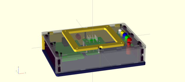
A big part of the combined electronic and enclosure design process was rendering the whole thing in OpenSCAD, my 3D design tool of choice. I personally find it really crucial to be able to visualize how all the parts will go together before I settle on details of a design. Here’s the final render I ended up with:
The hardware
On the inside, the components are simple by design. The brain of the whole operation is just a plain old Arduino Uno. I chose to use an Arduino as the driver for the programmer for a few reasons: I’ve used the ArduinoISP sketch a lot in the past very successfully; there was already existing code to convert an Arduino into a standalone programmer; the USB port and barrel jack were the only connectors I needed; and Arduinos are completely ubiquitous and easily replaced.
In addition to the Arduino, there are a few custom components. First, there’s a shield I designed that mates with the Arduino and provides all the connection adapters to the two other peripherals. It also has a handful of resistors for lighting the LEDs and a capacitor to suppress the auto-reset that occurs when a computer connects to the USB port – a must-have when operating as an ArduinoISP. Next is the interface board, which is basically just an LED array and the Go button – not much to see there.
The most interesting and challenging to fabricate component is the pogo pin array. I took inspiration on how to make this thing from a number of other pogo pin projects I’ve seen across the web. I made a point of breaking this out into a separate module so that I could isolate “fragile” electronics like the Arduino from any sort of mechanical stress. I found that setting the pin height was a little fidgety, and I’m going to experiment with alternative techniques for that the next time around.
The code
I based my programmer code very heavily on the existing AdaLoader project. However, there were a number of tricky issues I had to chase down to get it to work in my application. The original version was designed for flashing bootloaders onto ATMega168 chips, and there are some assumptions baked in to match that choice of target. Since I am flashing ATTiny44 chips instead, I needed to figure out the mismatches and update accordingly.
The first step was spending some time with the ATTiny24/44/84 datasheet to get some information like the chip signature. Next, I had to capture the hex file of my compiled code. The Arduino UI creates this file already, but it puts it in a random location every time. Finding it is pretty easy if you turn on the debug logging feature. (Basically, just set upload.verbose=true in your preferences.txt file.) After that, the path to the hex file is displayed in the window at the bottom every time you build/verify.
With the hex file in hand, I ran into my first real issue. For some reason, even though my program was actually laid out in contiguous memory, the hex dump produced by the Arduino IDE broke it up a bit towards the end. The AdaLoader code didn’t like this – it expected every hunk of data in the hex dump to be full and got confused when it wasn’t. I ended up writing a short Ruby script to transform the hex file into a clean, contiguous dump. I couldn’t quite figure out what I was doing wrong when trying to calculate the line-ending checksums, but I wasn’t really worried about data integrity between my laptop and the Arduino, so I ended up disabling that feature.
At this point I ran into my second issue – really, a pair of issues. What I was seeing is that the flashing would complete, but when the programmer read the bytes back to verify them, it failed, saying that the values were wrong. Uh oh. This was a real head scratcher for a while, so I spent some more time reading the datasheet. The first issue I found was that while the ATMega168 has a 128-byte flash page size, the ATTiny44’s was only 64. That was concerning, so I changed the settings, but the problem persisted. After reading the code very carefully for a while, I managed to debug it to point where it looked like it was flashing two different chunks of data to the same memory address. In fact, there was an odd pattern of alternating correct addresses and incorrect addresses aligned on 128-byte boundaries. (0x0 -> 0x0, 0x40 -> 0x0, 0x80 -> 0x80, 0xC0 -> 0x80…) This turned out to be because the target address was being masked with a pattern that aligned on 128-byte boundaries – clearly a relic of the code’s prior purpose. I just removed the mask altogether and all of the sudden everything started working!
What I have now is a device that can be powered by a simple wall wart and will program an un-flashed board in about 5 seconds, much faster than if we were doing it with the computer attached. Woo hoo!
There are a few next steps for this project before I’m considering it done. The programming part of the device is important, but so is the testing part. I’d like to figure out how to make the programmer put each newly-programmed board through it’s paces briefly so that we can identify defective boards early, before they are glued inside finished lamps. Also, there are a handful of places where the part tolerances of the laser-cut parts aren’t perfect, and making another copy gives me the opportunity to correct those mistakes. The version that I end up sending to China should be a bit more polished and feature-packed.