Most of the time when I’m driving an LED, I do it with a simple ballast resistor, and that’s all there is to it. Lately, however, I’ve been working on a few LED matrix projects, and while it’s certainly possible to use the same simple resistor approach, this leads to a very dim display. (Since any given LED’s duty cycle is 1/N max, they appear much dimmer than they normally would.)
The good news is that there’s a straightforward solution to this problem. LEDs have a rated forward current, but they also have a rated peak current, specified at a given pulse width and duty cycle. For instance, these red LEDs are rated for 30mA forward current and 185mA peak in 0.1 ms pulses at 10% duty cycle. Why is this stat useful? As long as you stick to the pulse width and duty cycle parameters, you can intermittently drive an LED at an excess current and get a brighter light without burning it out.
There is a risk in using this setup, though. If for some reason your PWM signal were to lock up in the “high” state, then the pulse width limitations would be exceeded and you’ll probably fry the LED in an instant. This means you need to be especially cautious during development – crashing your microcontroller at the wrong time can be costly!
While the theory of this is straight-forward, I wanted to test how it actually looks in practice before I integrated it into my design. If it was only moderately brighter, I didn’t want to spend the energy (and money) on adding an array of transistors to my board.
My test setup.
I decided to throw together a test setup that would allow me to compare brightness of an LED at its full-on steady current, one PWM’d with a ballast resistor to keep it at its steady current, and one at peak current and PWM’d. This sets up a comparison between the maximum brightness, the brightness of the same LED in a naively driven matrix, and finally the same LED over-driven.
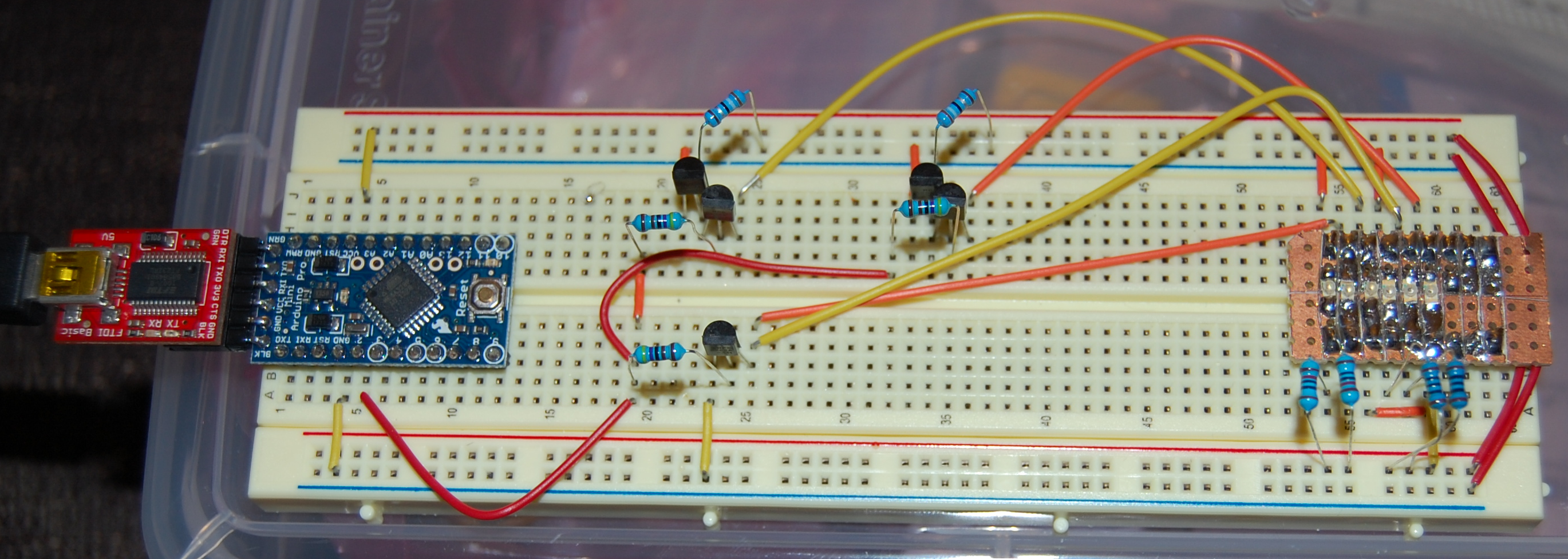
The LEDs I’m using here are surface mount in a 1206 package. Saying that they are very small is an understatement. They are by no means breadboard compatible, so the first step was creating a simple breakout board.
I used a piece of pre-drilled perfboard with a solid copper pour on one side to make the breakout. I marked off a few columns of 6 holes each so that it would span the IC gutter on a breadboard, then cut the piece out with a pair of aircraft snips. Next, I used a utility knife and a straightedge to score the copper and separate the columns from each other, and then did one horizontal stroke to make a grid of 1×3 hole pads.
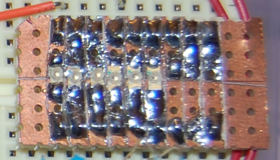
Detail of the LED breakout board
Next, I soldered two rows of 0.1″ header to the top and bottom of the board for mating with the breadboard. Then, I hand-soldered 6 LEDs, 3 red and 3 green, onto the board. (Judicious use of continuity tester and solder sucker not optional.) Finally, I used a file to chop one corner as an orientation indicator and then cleaned up the rough edges.
To prove that everything was working, I started out by connecting the steady current resistor and probed all the LEDs. Everything lit up fine. With the baseline established, the next step was to set up the PWM signal. According to this page, the Arduino’s built-in analogWrite() PWM runs at about 500Hz, which is too slow for the target pulse width. Since I didn’t need crazy precision or performance here, I decided to quickly write up an Arduino sketch that toggled the output pin manually and used delayMicros() to set the interval. The sketch turned out to be pretty simple:
[gist https://gist.github.com/bryanduxbury/7729613]To verify that this was giving the output I expected, I hooked up the output pin to my handy DSO Nano. On the first try I ended up with a 996 Hz frequency and good pulse width. The error in the frequency is probably due to the fact that there’s overhead to toggling pins and calling delayMicros(). I suspect I could dial it into precisely 1000 Hz by guess and test on the delay durations, but it’s not that important at this point. In the real production scenario, I’ll be using a hardware timer and it’ll be worth getting it exactly right.
Connecting the PWM output to the second LED was straight forward, though I did add a NPN transistor in between the output pin and the LED so that it could drive all the PWM inputs without any worries about current draw.
The over-driven LED was the most complicated to set up. I plugged the peak current number into an LED resistor calculator, and it told me I needed a 12 ohm, 2 watt resistor. Yikes! I certainly don’t have anything like that on hand. Rather than putting a whole ton of resistors in parallel, I wired up a simple constant current LED driver circuit using some common transistors and resistors. I’ll leave the discussion of that driver circuit for another time, but the cool thing about it is that it allows the transistors to do all the heavy wattage dissipation while the resistors see a tiny load.
With everything wired up, I powered it on to assess the results:
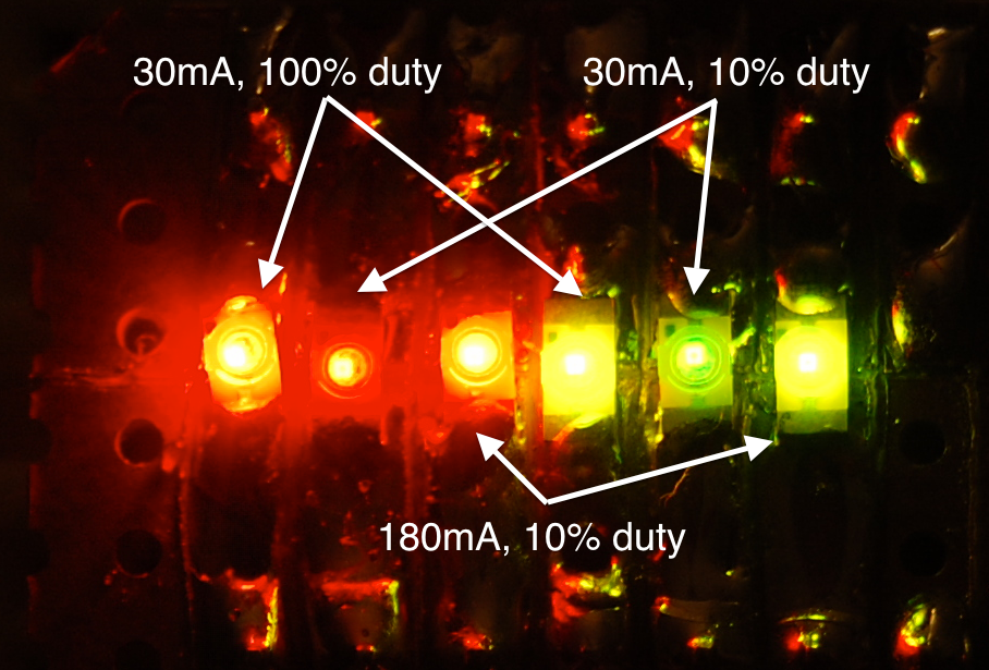
- Closeup of the final brightness test. Hooray for DSLR cameras!
I would say that the PWM-only LED is substantially dimmer, and the overdriven LED is almost but not quite as bright as the steady-on LED. This turned out to be exactly the sort of obvious difference I was looking for. It seems well worth adding the additional circuitry to get a much brighter display.

Pingback: Advice About Over-Driving LEDs
Pingback: Belgaum news | About Belgaum | Belgaum information | Belgaum district | Belgaum city | Belgaum Hotels | Belgaum People | Belgaum tourism | Belgaum entertainment | Belgaum students | Inside facebook | Hack | make use of | technical news | | Advice About Ov
Pingback: Advice About Over-Driving LEDs | Hack The Planet
” LED resistor calculator, and it told me I needed a 12 ohm, 2 watt resistor”
I guess that the calculator did not take in account the 10% duty-cycle. So a 1/4 watt resistor was probably just fine.
I think you’re probably right. I didn’t think to look in the datasheet for my resistors to see if they have a similar pulse behavior until after I’d built the constant current driver.
Resisitors are simple devices, if you put in 2 Watt for 10% of the time, they see 0.2 Watt. At least if the frequency high enough. Don’t try it with 0.001 Hz 🙂
I would place an arrow or mark of some sort on the LED Photo.I have no idea which LED you refer to or even what colour of each in the photo . Perhaps a video might be better but definately say which LED is which
Good call! I updated the image with some text and arrows. Hope that helps!
The only problem with this technique is if the firmware gets lost and stops the multiplexing process, the display over-currents and is damaged. Dealt with this years ago, driving VFD’s. Added a hardware retriggerable one-shot (watchdog), driven by a data strobe, which enabled the output driver. In case the firmware goes nuts, the one-shot times out, killing current to the display, preventing display damage. Otherwise, a minor firmware bug could ruin a whole bunch of LEDs before you could hit the off switch.
Wow, this is a pretty cool idea. I’m not sure exactly how it will fit into the design I have in mind just yet, but I’ll think about it!
Pingback: Advice About Over-Driving LEDs | Maker of Meta
ok a little lost you talk about over driving leds for brightness but in the results :I would say that the PWM-only LED is substantially dimmer, and the overdriven LED is almost but not quite as bright as the steady-on LED. This turned out to be exactly the sort of obvious difference I was looking for. It seems well worth adding the additional circuitry to get a much brighter display.” you say the steady on is the brightest?
so you say over driving for brightness but then your results “I would say that the PWM-only LED is substantially dimmer, and the overdriven LED is almost but not quite as bright as the steady-on LED. This turned out to be exactly the sort of obvious difference I was looking for. It seems well worth adding the additional circuitry to get a much brighter display.” you say the steady on is brightest
Great comparison, but I don’t get your conclusion. If steady on is brightest, isn’t that the best choice? Thx
Yes, but in LED matrices, you usually strobe the grid and rely on persistence of vision, rather than powering each LED individually. This decreases the overall power draw, but more critically reduces the number of microcontroller pins required to operate it. So by over-driving the LEDs, you make them substantially brighter during the fraction of a second that they are on, making up for the fact that they’re operating at a substantially lower duty cycle.
I am a retired engineer but still keeping tabs on companies who advertise SMD LEDs at a brightness rating which I believe is a straight lie, or they are overclocking the LED. If I use a chip with 600mcd Red + 1350mcd Green and 280mcd Blue the total is 2,230mcd or 2.23cd.
If the driver is working at 1/2 scan then that makes total 1.115cd.
10,000 chips per sq Mtr makes total lumens 11,150 or 11,150 NIts.
This would just be a bright unintelligent light.
To be part of a large format Video Display (say 100 Sq Mtrs) it would probably only ever show 50% or 5,575 Nits.
Am I correct to think this way ?
Your math seems at least directionally right, but I’m not knowledgeable in the area of displays!