For my recent Question Block Lamp project, I wanted to be able to play sound effects. Initially I was a little concerned that it would be difficult, but after I found the awesome Mario Piano Sheet Music project and Arduino’s tone library, it looked like everything was going to be super easy!
However, after writing the code and wiring up the circuit, I ran into a little problem: the sound that came out of the speaker was too quiet. It was audible, but wasn’t exactly robust, and that was with it into my breadboard. Installed, the speaker was going to be stuck on the inside of a 3mm acrylic box, so it seemed like there was significant risk of the sound effects being inaudible.
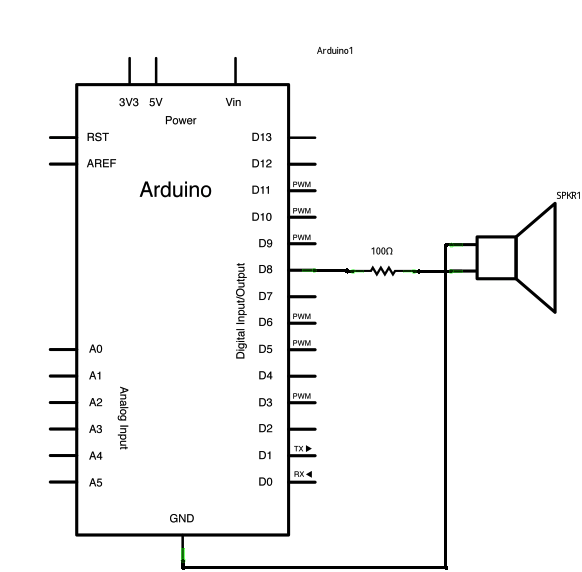
Sound volume is directly proportional to current. When you’re hooking up a speaker to an Arduino as described above, the reason for the softness of the sound comes down to the fact that the digital out pins on AVR microcontrollers (ATMegas for official Arduino boards, or the ATTiny in my case) can only source or sink around 50 mA, which is why the tone examples have you hooking up the speaker through a 100-ohm resistor. Most speakers, including the cheap ones at RadioShack, can handle a lot more current than that, and without the resistor you’d probably fry the pin on your microcontroller.
So the problem has an obvious diagnosis, but what about the solution? I’ve read about audio amplifiers in the DIY context in the past, but truth be told all that did was make me nervous. I thought it was likely to be complex, require a number of additional components on the board, and would add cost to the project.
Yet again, it turns out that I was over-thinking the problem. In most cases where you need to use a professionally designed audio amplifier, the audio is a complex waveform, and the way you amplify it can radically change how it sounds. But when you’re using Arduino’s tone library, your waveform is actually incredibly simple: it’s nothing more than a square wave that swings from +5v to ground on the frequency of the note you’re playing.
What’s so great about that? All you need to do to amplify the current of a square wave is a single transistor. It’s really easy to wire up: just connect the Arduino’s output pin to the transistor’s base pin through a 100-ohm resistor, then the collector pin to +5v and the emitter pin to the speaker’s + lead.

This solution costs almost nothing and is staggeringly effective. When I tested it, there was a clear, significant volume increase. Even from inside the sealed box, it was more than loud enough to get the job done. Isn’t it great when things work out so well?

Ifound my way to finish all the steps you wrote on the arduino. what is arduino
something else you might try with the speaker. Connect it to VCC instead of GND. The avr used in the arduino can sink more current than it can source so you can use a smaller resistor and get louder output.Just a thought,[:Ray Moore
@Farldarm – that would be a good way to get it a little louder without any additional parts. Great tip.
Does it matter if the speaker is on the high side or low side of the transistor?
@George – I don't think it does. Either way, current is only going to flow through the speaker when the transistor is on.
I think George has raised a valid point. NPN BJTs are better at sinking current than at sourcing. I too am of the opinion that you may get slightly better performance if the NPN emitter is grounded and the speaker is connected from Vcc to the collector.
Brian,Looks like an elegent solution for amplication. However I am new to this and did not quite understand your connection instructions.I assume from your diagrem that VCC and GND on the ATTINY go to Arduino pins 8 & 4 respectively.I see Pin 6 connected through the resistor. You then say "collector pin to +5v and the emitter pin to the speaker's + lead.I don't quite understand this:Could you help me by spelling out in more detail what the other end of the resistor is connected to. ie what is the +5v connection and GNDA connection.As you might gues I am a software person with limited H/W knowledge.Thanks
Hi,I am running a little 8 ohm speaker with the transistor as you suggested. It works great but it is getting quite hot. Do you have this problem?
Hey Georgia – Which component is getting hot, the speaker or the transistor? You should make sure that both components will be capable of handling the amount of current you'll be passing through it. For the transistor, make sure that the collector-emitter current is high enough, and for the speaker make sure that the max wattage is greater than the amount you'll need.
You are letting a large DC component through the speaker; that is why it is getting hot.
Indeed; experimentally I see 2 amps at 6 volt power supply. Assuming that the purpose is just to reproduce square waves is there a shortcut or is it necessary to bias the transistor to be non-conducting when the has the voltage low on the base resistor? Can that be accomplished with a voltage divider of resistors between the supply voltage and base and base and ground?
I need to withdraw this comment. The issue turned out to be a poorly placed test lead. Correcting that I do not see any large current drain. I thought I was seeing the current drain described by Alex D. BTW I am using a 2N3904.
you need a diode across the speaker or risk killing the transistor
Works like a charm. Added a led in the output connection to make it possible to go silent but still “see” beeps.
Is it not necessary a decoupling capacitor? Thanks
Hi there, I’m new to this game. From the ATTiny where do pin 4 & 8 connect to on the Arduino, is it the VCC & Ground pin on the Arduino?
ATTiny VCC and Ground should be connected to Arduino VCC and Ground respectively.
hi there, thanks for the tutorial! for now I was trying to connect the speaker straight to the pin 9, without resistor. however I basically only hear noise coming out from it..do you know what could be the cause? thanks!
The pin on the microcontroller can’t drive a huge amount of current, so that might affect your output volume. It also might not be in “output” mode. But other than these guesses, hard to say without a schematic and a sketch!
Hi there..thank you for the reply..it was a really silly mistake..I didn’t read about the sound format required by the library..once that was fixed everything was ok..one tip that might be useful for others..if the song contains metadata there will be crackle noise at the end of each song. Removing them (audition can do this easily when exporting) will solve the issue. too bad the quality required is so low ;/ thanks for your help!
Hello Bryan! Thanks for this awesome tutorial. I did’t try it yet but i was thinking if I should add a filtering circuit prior amplification? I am generating PWM audio through arduino (8 bit 8kHz mono) and it sounds a little bit noisy. i already tried RC filter with different cutoff frequencies, but i don’t see any change in the noise. Only the output would decrease (if i use higher R value). So while considering amplification using your method, i am guessing it would also amplify the noise, which won’t be nice for me :/.
Thanks
Yeah, this setup will only make your audio louder, not less noisy. You probably want to use something like an op-amp-based 2-stage low pass filter if you want to remove high-frequency noise.
where did you read ~50 mA per pin?
Click to access atmel-2586-avr-8-bit-microcontroller-attiny25-attiny45-attiny85_datasheet.pdf
on page 161: absolute max. ratings dc current per i/o pin is 40 mA
Pingback: BLOG WEEK 9 – HELI7544, YCHE3721, XNAN0177 – IDEA9102 IDEA STUDIO 2017