I’m a big fan of the Dune series, so when this post about the Thermal Grill Illusion popped up in my feed reader, I was immediately hooked. For those of you who are not acquainted with the Dune franchise, the “pain box” – which is never actually named in the series – is a device which causes an excruciating burning sensation without actually producing any injury.
Why is this a cool thing to have in the real world? Well, first, it’s an homage to the series, and I imagine other fans will get a kick out of it. Second, I find the idea of having a source of injury-free pain intriguing from a willpower standpoint – how long can you intentionally experience discomfort, even if you know it’s causing you no damage? Lastly, constructing it requires a mixture of electronics, mechanical engineering, and presentation, which puts it squarely in the middle of all my interest categories.
Overall design
What I’m going for is an enclosed box with a hand-sized (4″ x 8″ x 3″) opening. The bottom of the opening will be the illusion surface – what I’m referring to as the “radiator”. The box should be as small as possible for portability and overall presentation. It will have to be plugged in from a power consumption standpoint. It needs to be able to produce a hot temperature of ~41 degrees C and a cold temperature of around 18 degrees C, and I’d prefer not to use large reservoirs as the heat source. (See portability requirement.) Also, this device has potentially weird safety aspects, so it needs to be designed such that it’s hard for it to actually hurt someone. This means temperature feedback and some way to remove danger or alert the user. And lastly, I’d like to be able to make it on my Shapeoko 2 CNC machine, which limits the size of any single component to about 12″ x 12″.
Given that I’m going for compactness and simplicity, the most obvious source for both heating and cooling is a device called a thermo-electric cooler, sometimes called a Peltier. The basic concept is that it’s a solid state heat pump, where heat is pumped from the cold side to the hot side. The colder you make the hot side, the colder the cold side will get. Flip the direction of the current, and the device reverses the flow of heat.
How exactly the heat from these devices will be transferred to a user’s hand is still up in the air. Generally speaking, achieving the desired temperatures and making sure they get to the user is really the core challenge of the whole device. The rest is just tidiness and presentation.
Version 1 (Failed)
Immediately after I decided to use TECs for my hot/cold source, I bought a 5-pack of them from Amazon. (I was surprised by how cheap they were, but it turns out that might not have been a good thing. More on that later.) The next question is how to distribute the hot and cold. I’ve got a fair amount of experience making printed circuit boards on my CNC, and I know that lots of people make PCB heater boards (commonly seen on 3D printers, for instance). If a PCB could transmit heat, why not cold as well?
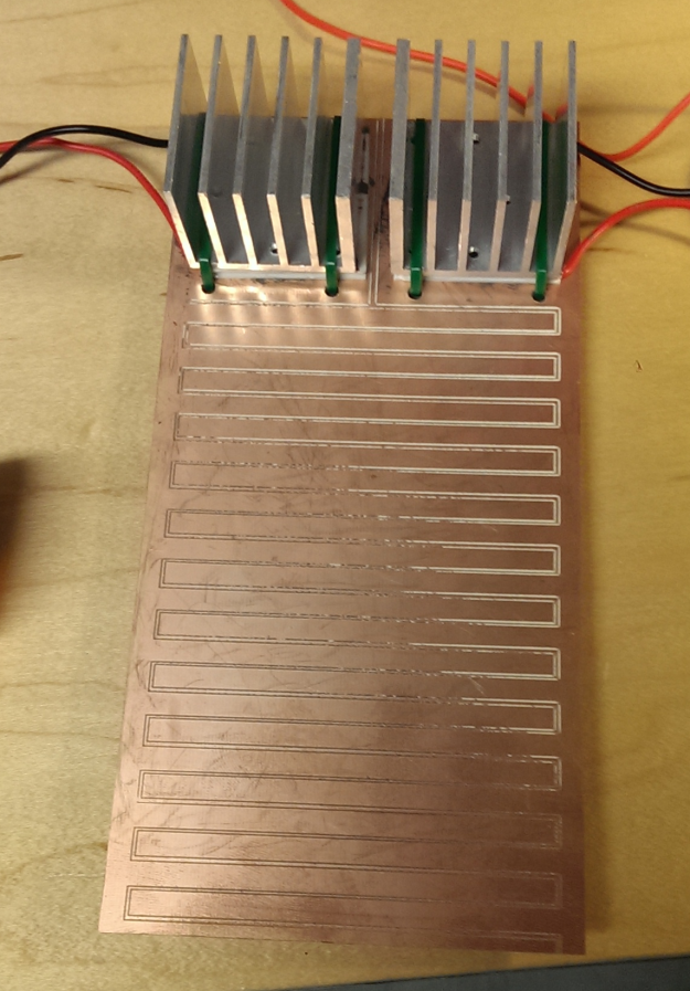
I designed a very simple PCB that is really just two large, interleaved copper pours connected to a space for a TEC and heatsink. The idea was that heat or cold would flow through the copper, since it’s highly conductive. It’s also a crazy simple and compact design, so I was pretty excited to produce it. Here it is, all assembled:
Turned out great! Except it completely failed to transmit heat. In fact, while the pours basically stayed at ambient, the back side of the board right under the TECs got really hot or really cold! It would seem that the thickness of copper on a standard PCB blank is way too thin to be a good conductor. Oh well, into the bin and onto the next alternative.
(Side note: the PCB heaters I alluded to earlier are not radiators of heat per se. The current being pumped through the traces on the board is what actually creates the heat in the first place.)
Version 2 (work in progress)
The new design I’m working on now swaps the PCB radiator for one made of copper tubing. Small diameter copper tubing is very affordable, easily cut and bent, and highly heat-conductive. To actually deliver heat/cold to the array of tubes that will make up the radiator, I’m using two closed-loop water heater/chiller systems.
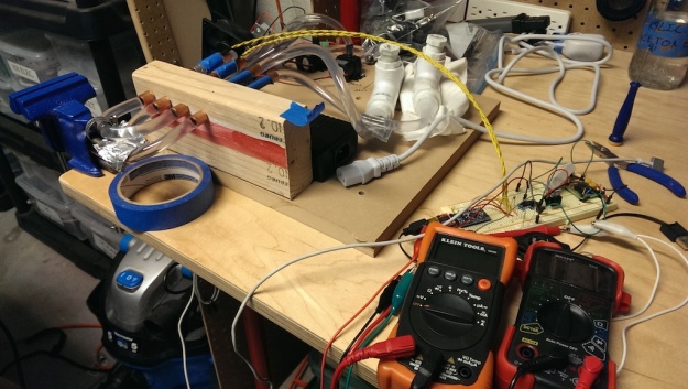
For each loop, the basic design is a TEC strapped to a water block, with the loop looking like water block -> radiator -> simple reservoir -> aquarium pump. The TEC on each loop is configured to either heat or cool the water, which in turn heats or cools the copper tubes. Here’s my bench test of this setup:
Note that my radiator is currently a proof of concept made from 3/8″ copper tube sections bridged together with 5/16″ ID vinyl tubing. I’d hoped that this tubing technique would replace the need for expensive copper plumbing fittings, but unfortunately the tubing kinks at a much larger radius than i’d like to have for good spacing. I also bought a cheap tube bending tool with the hopes that I could use that to make what I need, but discovered that the tube bender also had an overlarge bend radius! For now, I’m going to leave it alone and brainstorm alternatives.
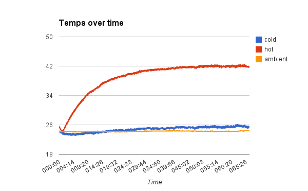
While early qualitative testing was promising, it’s certainly not producing the level of discomfort I’m hoping for. (Ha.) Two major problems here: the hot side actually eventually gets too hot, and the cold side never quite gets cold enough. To help quantify this poor performance, I wired up a pair of thermistors and an Arduino Pro Mini to serve as a temperature logger. Here’s what the data from that logging session looks like:
Good news: the hot side gets hot. That is the end of the good news. Bad news: it takes over an hour for the hot side to reach its apparent max temp of 42.4 degrees C. Worse news: the cold side does awful. It gets a teensy bit cold during the first few minutes, but then eventually actually starts to increase the temp over ambient in the long run!
I think this poor performance reflects a handful of problems:
- The hot loop just doesn’t have the pumping ability to move heat fast enough. The cold side of the TEC gets pretty cold, and that’s probably because the water in the hot loop makes up a pretty decent heat sink, even without an outlet for all that heat.
- The cold loop doesn’t have powerful enough heatsinking on the hot side of the TEC to overcome the self-heating effect. This explains the slight drop and then long-term rise in temperature. It is also entirely possible the cold loop TEC has burned out due to overheating.
- There is probably too much water in each loop. Between the lengths of tubing and the fairly oversized reservoirs, this is adding more mass that has to be heated or cooled, slowing down the desired temp changes.
- The TECs I bought are under-rated for what needs to be done. I’ve been reading accounts of folks who turn on their TECs and immediately see frost on the cold side, and I’ve never come close to seeing that.
Overall, despite flaws, this design seems like it has promise. The next steps are:
- Experiment with a more expensive / higher rated TEC unit to see if the performance is better. We’re only talking like $12 each here, so not a deal breaker.
- Replace the janky heatsink/fan combo on the cold loop with something professionally designed to remove a lot of heat.
- Experiment with running two TECs and waterblocks both in serial and in parallel to see if it improves the time-to-target-temperature and max delta-T
- Prototype a feedback controller to allow each loop to hold a target temperature
- Experiment with techniques to make a denser radiator grid


Pingback: Making the Dune “Pain Box” a Reality | Hackaday
Pingback: Making the Dune “Pain Box” a Reality | Hack The Planet
How about running the water on both sides of the TEC? Have the cold loop run water on the cold ends of each TEC, and the hot loop running water on the hot ends? I’d keep the hot and cold water in separate reservoirs, too.
If I use one TEC to create both the hot and cold temperatures, then I lose the ability to get the exact target temps I want. (A TEC produces a temperature delta between its two sides, but the actual temps depend on the current ambient temp.)
The hot and cold are in completely separate loops, including separate reservoirs.
I love this idea!!! Let’s start the Bene Gesserit school up.
Have you thought about trying heat pipes instead of the water cooling loop. Much faster response times and no extra pumps needed. Another thought would be using the hot/cold heatsinks directly as the grid. A decent PWM circuit (maybe Arduino or similar driven) could easily control this, allowing variable output.
I thought of heat pipes, but got the impression that they had a fairly complex internal structure. Any tips on where to find plans for a DIY heat pipe?
Unfortunately, TECs don’t like PWM control. I’m designing a PWM-controlled analog current sink to drive these devices.
OK, taking a wild stab at this: I see you have heatsinks with nice wide parallel gaps. So how about doing the following:
1. Saw and sand the heatsinks down so the fins are about as hight as the spacing between the fins.
2. Mount the TECs so that they cool the heatsinks. These will be the cold part of the grill.
3. Fill up the spaces between the fins with balsa/foam/whatever. This should insulate them a bit and support the wire in step 4.
4. String a nichrome wire so that you have a nichrome strand centered between each protruding fin, lying on top of the balsa/foam.
Nichrome wire is quite easy to directly control, since it heats up proportionally to the voltage applied, and I think you’re not gonna need much voltage. Maybe 1 or 2 volts.
I would also heatsink the warm side of the TECs to get rid of the extra heat.
Both the nichrome and TEC can be driven easily via 2 LM317s from a 12v source, I think.
Should be simple to set up a small proof of concept, and then expand to more heatsinks and nichrome for the full-scale setup.
I had similar issues. I think the better way would be to use a ice maker compressor. The hot is hot, the cold is cold and it gets up to temp relatively quickly.
Pingback: Pain box part 2: When in doubt, add watts | Bryan Duxbury's Blog
Pingback: Painbox part 3: a bunch of updates | Bryan Duxbury's Blog