I’m designing an LED matrix clock that plays Conway’s Game of Life to evolve a representation of the current time. See the whole series of blog posts about the project here.
At the heart of this project is the PCB. I set out to push my limits a bit, and I certainly succeeded at that. This is by far the most complex board I’ve ever worked on, owing mostly the sheer number of components (132 LEDs, 14 resistors, 4 capacitors, a crystal, a microcontroller, and a linear regulator) crammed in such a small space (25 x 100 mm).
The basic layout is that the front of the board is the LED matrix, while the back hosts all the support circuitry. Let’s look at each of those in turn.
The matrix

Laying out a grid of LEDs should be easy, right? Well, not that easy. Immediately after I got done drawing the schematic for the matrix, I discovered that the LEDs I selected simply weren’t going to fit in the available space. Faced with the prospect of 132 separate REPLACE commands, I quickly developed the beginnings of what I’m now considering my EAGLE secret weapon: what I’m calling external scripting. I wrote a simple Ruby script that generated all the names of the LEDs, and then piped that through some bash magic to compose the commands I needed. Once I pasted the results into the EAGLE command bar, boom, all LEDs replaced in one fell swoop.
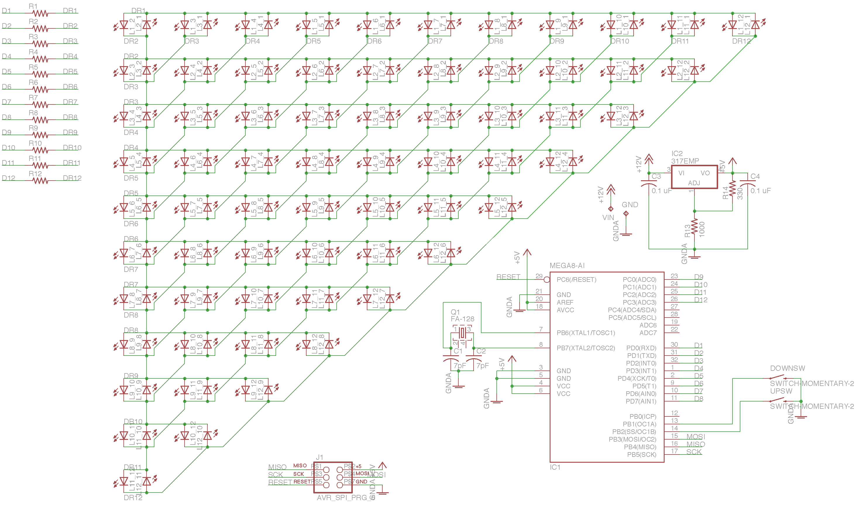
Not an easy schematic to draw. Yes, I did it by hand.
This technique worked so well that I knew I’d take advantage of it again. I didn’t have to wait long. As soon as I switched from the schematic to the board, I found myself needing to actually position the LEDs. I tried making the grid match my desired spacing, but that was proving too tricky, especially when combined with having to position all the LEDs in a precise order. Scripting to the rescue!
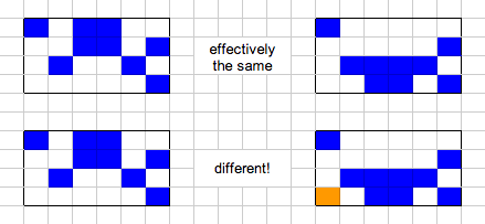
A word on the LED layout scheme
A quick aside: at this point in the project, I had to decide on a layout scheme for the LEDs that both made it easy to route the board as well as write code to map the LEDs into a 2D grid. Charlieplex LEDs are addressed by (high pin, low pin) pairs, but I’ll need to interact with them from a more (x, y) perspective. This would not be something easy to change later, as its encoded in the hardware itself.
I elected to go with a strategy that put high/low pairs and their inverse next to each other, thinking that this would limit the number of far-flung connections needed. These pairs are laid out in a sort of round-robin fashion so that they’re all exercised. The result ends up looking like this:

Anyways. Using the earlier technique, I wrote another Ruby script that generated EAGLE commands to position all the LEDs according to this scheme. The scripting here was really crucial, because I had to try out multiple tweaks before I got everything just right, and without a script, I would have been committing to several hundred clicks per experiment!
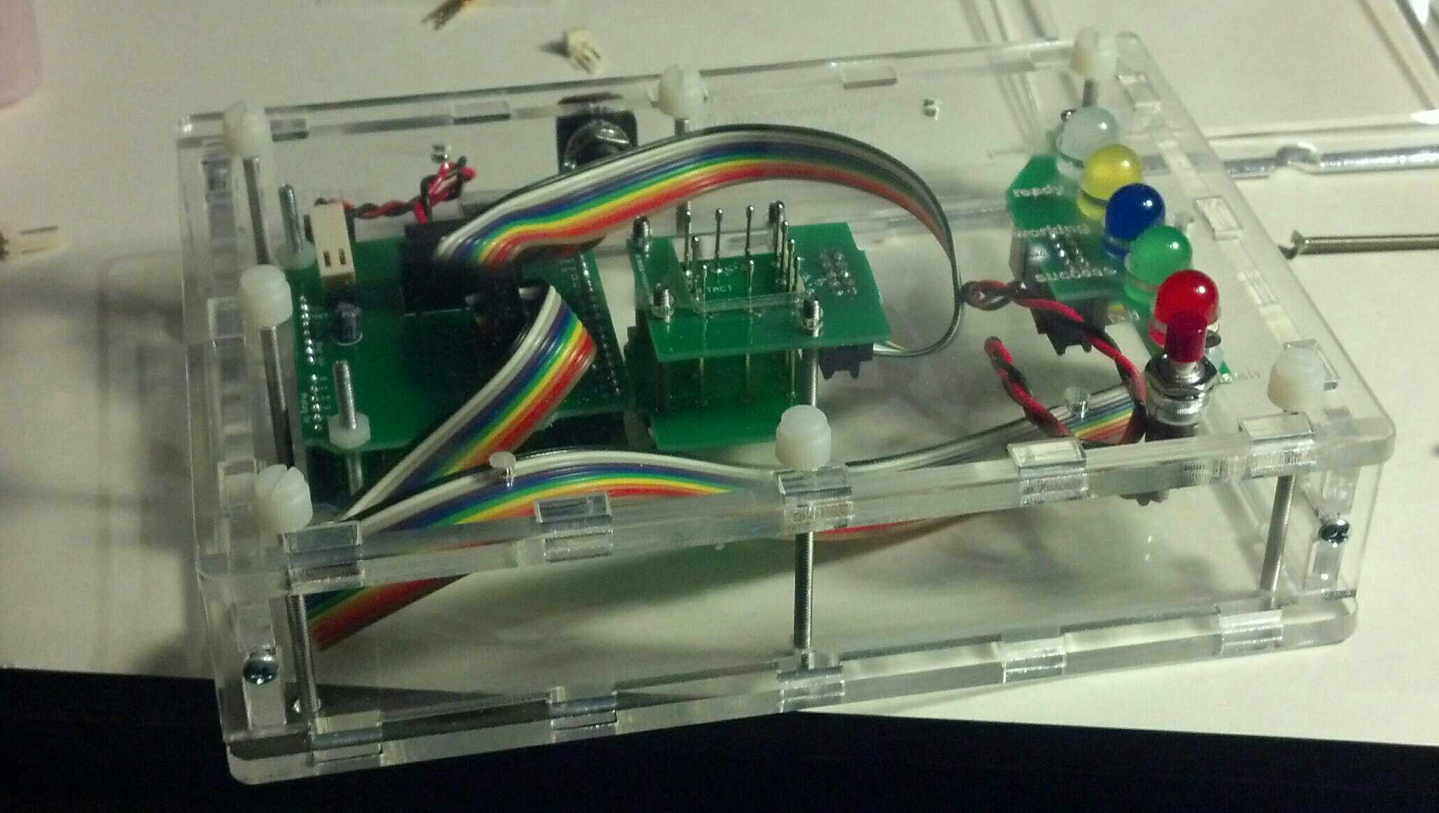
Supporting electronics

The ATMEGA is the centerpiece of the back of the board. Nearby is the 16MHz crystal, and to either side are the momentary switches that allow the setting of the time. The top edge of the board is the bank of current-limiting resistors needed to drive the LEDs. Finally, on the edges of the board, there’s a 6-pin ICSP programming header and your standard LM317 linear regulator circuit set up to output 5V.
A note on the power supply. I don’t think this thing is going to be a power hog, and I’d ultimately like it to be pretty compact and beautiful, so I’m planning to just stick a 9V battery in there and call it a day. This is sorta phoning it in, but since the ICSP header breaks out the 5V bus, I figure I can always solder in a USB cable and power it from a wall wart if I have to.
Putting it together
I sent the Gerber files off to Seeed Studio’s FusionPCB service for production. About a month later, the boards turned up, and I couldn’t wait to assemble them.

When reading about other folks’ LED matrix projects online, a common complaint was that it was difficult to get all the SMD LEDs aligned properly without some sort of jig. I didn’t want to mess around with creating a special fab tool, so instead I made the conscious choice to go with solder paste and hot air reflow. The idea was that I’d get the automatic alignment effect that solder paste + hot air exhibits.
Here, I made a miscalculation. Instead of making a solder paste stencil and applying it with a putty knife (which I’ve done before!), I decided to just dispense the paste directly from the syringe. This was a disaster. The paste I have has gotten kind of old, making it less apt to flow out the tiny syringe tips I have. Plus, I somehow lost the plunger that came with the paste, and was stuck using a Sharpie marker as a makeshift plunger. Not what I would call ergonomic. Still, this might have been OK for a few tens of pads… but I was applying paste to both sides of 125 LEDs! It took well over an hour, and by the end, I was in a lot of pain and didn’t have the patience to do it correctly. Consequently, a lot of the later LEDs got a huge glop of paste that sometimes bridged their pads and was just generally poorly done.
Populating the board was painstaking, but nowhere near as difficult as the pasting. When it was done, I fired up my trusty heat gun to reflow the board. About 85% of the LEDs did exactly what I was hoping for and sucked themselves right into place, but the rest pulled away from their pads, tombstoned, or clearly bridged under. I ended up spending another hour or so just going through and doing rework on the bad LEDs.

With the matrix side behind me, I turned my attention to the back of the board. At this point I was pretty done with solder paste, so I switched over to the iron. First up was the microcontroller. I used the “flow and wick” technique, which worked like a charm – after I refreshed my memory from this excellent SparkFun tutorial. (Heres a better video that illustrates the technique more closely.) The rest of the components were no problem – I just tinned the pads, positioned the components with tweezers, and then reflowed the pads until the pieces stuck. The one exception here was the crystal, which doesn’t have any exposed leads. For this guy, I just tinned the pads, then positioned the crystal and hit it with the hot air gun. I was relieved when I saw the crystal shift and adjust itself into place. Phew.

Turning it on
With the board fully populated, it was time to turn it on. It’s always scary to do the first power on test of a new project, particularly one where it’s impossible to do incremental tests. I flashed a spare Arduino with with ArduinoISP sketch, hooked it up to the programming header, and proceeded to burn a bootloader. Astoundingly, it worked the first time!
Next, it was time to test the matrix itself. I had already developed a Charlieplex matrix driver during my minimal prototyping stage, but the new board was really different and needed a new driver. But before I dove into porting the complex logic onto the new board, I wrote a trivial sketch that just exercised all the LEDs in sequence by manually toggling the pin pairs according to the scheme described above.
Guess what? It didn’t work. At least, not all of it. There were numerous spots in the matrix where LEDs were skipped, and a few spots where instead of a single LED lighting, multiple LEDs would glow dimly. It turns out there were a few problems here. The first was that my test sketch accidentally referenced the same pin twice, making it do a weird rewind-stutter thing during the test sweep. That one took an embarrassingly long time to find. With that software error out of the way, I proceeded from one LED to the next, debugging each misbehaving one. A few of the LEDs were in backwards – a population error. Some just seemed to be busted, and worked after replacing with a spare. Whether they came off the reel that way or were damaged during reflow, who knows.
By the end of the night, I was done debugging and all the LEDs worked as expected. Hooray! No disastrous issues! Now, I could finally start on the actual production sketch.

 It’s hard to be 100% sure if I took the same approach as Duparc, since his original research paper is written in French. The way my algorithm works is to divide the grid in half vertically again and again until I’m working with single columns, at which point I essentially rotate the column into a row apply the same subdivision algorithm again until I reach a single cell. Single cells – both alive and dead – have a nice, cacheable method for determining all their prior states. Once I have the partial answers for a single cell, I intersect them with the answers from the neighboring cell by checking the overlap between the two. If the cells shared by the two possible solutions match, then the combined solution is also viable. Partial solutions that don’t match neighbors are discarded. This same process of merging based on overlapping cells continues back up the search tree until we reach the root, at which point we have a set of possible prior generations.